An ER diagram (entity relationship diagram) shows what a database stores and how it fits together. Each box is an entity, such as a customer or an order, with its attributes and keys; each line is a relationship, and the symbols at its ends say how many of one entity go with the other. Database courses ask for one in almost every assignment, and developers sketch one before writing a schema.
Below are 12 ER diagram examples in crow's foot notation, from a three-box starter to a hospital, a bank and an airline. Each was made with Eidora's ER diagram generator from the text shown under it, and each comes with its solution: how to read every relationship in it. We checked every line against its text. Press Use this text under any example to open the generator with that text, change it, and get your own diagram in under 30 seconds.
Make your own ER diagram
Describe what your system stores and how things relate, give a topic, or paste CREATE TABLE statements. The ER diagram generator opens with your text in its box; press Generate there to draw it.
Free to try: one diagram a day without an account.
How to Read an ER Diagram (Crow's Foot Notation)
Each box is an entity: something the database keeps a table for, such as BOOK or MEMBER. Each row of the box is an attribute: its type on the left (int, string, date), its name in the middle, and its key, if any, on the right.
PK, FK and UK. PK is the primary key, the column that tells the rows apart (usually id). FK is a foreign key, a column that points to a row of another entity: customer_id in ORDER points to a customer. UK means unique: no two rows have the same value.
Each line is a relationship, labelled with a short verb phrase. The symbol at each end says how many of the entity at that end go with one of the other:
Two short bars: exactly one
A circle and a bar: zero or one
A crow's foot and a bar: one or more
A crow's foot and a circle: zero or more
Read each end from the other side. In example 2, the line from CUSTOMER to ORDER has two bars at CUSTOMER and a circle with a crow's foot at ORDER: each order has exactly one customer, and a customer has zero or more orders. The entity at the crow's foot is the one that holds the foreign key (ORDER has customer_id).
1. Simple ER Diagram Example: Authors, Books and Publishers
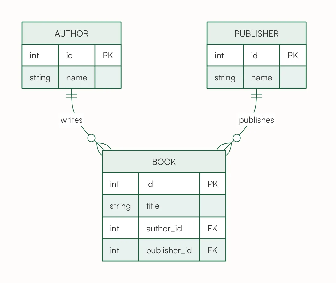
The smallest useful ER diagram: three entities and two one-to-many relationships. Solution: each book has exactly one author and exactly one publisher, so BOOK holds both foreign keys, author_id and publisher_id. An author writes zero or more books, and a publisher publishes zero or more, which is why the crow's feet are both at BOOK.
Real books often have several authors. That needs a table in between, as in the library example below.
Text used for this chart
Simple ER diagram: an author writes many books, and each book has exactly one publisher.
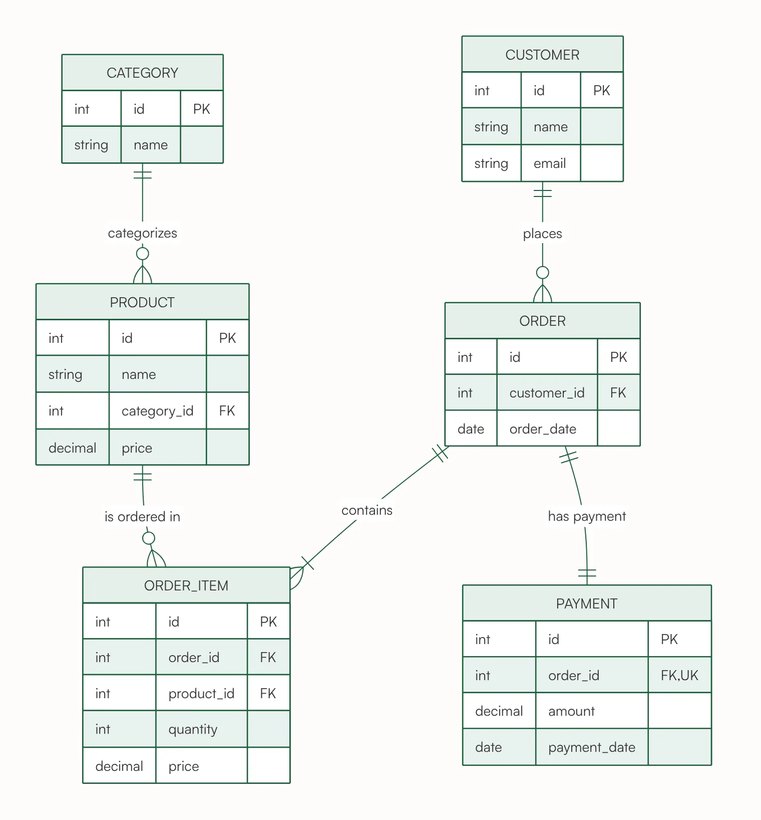
The classic e-commerce design. Solution: a customer places zero or more orders, and each order belongs to exactly one customer. Each order contains one or more order items: the end at ORDER_ITEM is a crow's foot with a bar, because the text says "one or more". Each order item is one product, and a product can appear in zero or more order items, so ORDER_ITEM is the table between orders and products, with its own quantity and price. Each product belongs to one category.
ORDER and PAYMENT are one-to-one: bars at both ends, and order_id in PAYMENT is both a foreign key and unique (FK, UK), so no order can have two payments.
Text used for this chart
Online store: customers place orders. Each order has one or more order items, and each order item is one product with a quantity and a price. Products belong to a category. Each order has one payment.
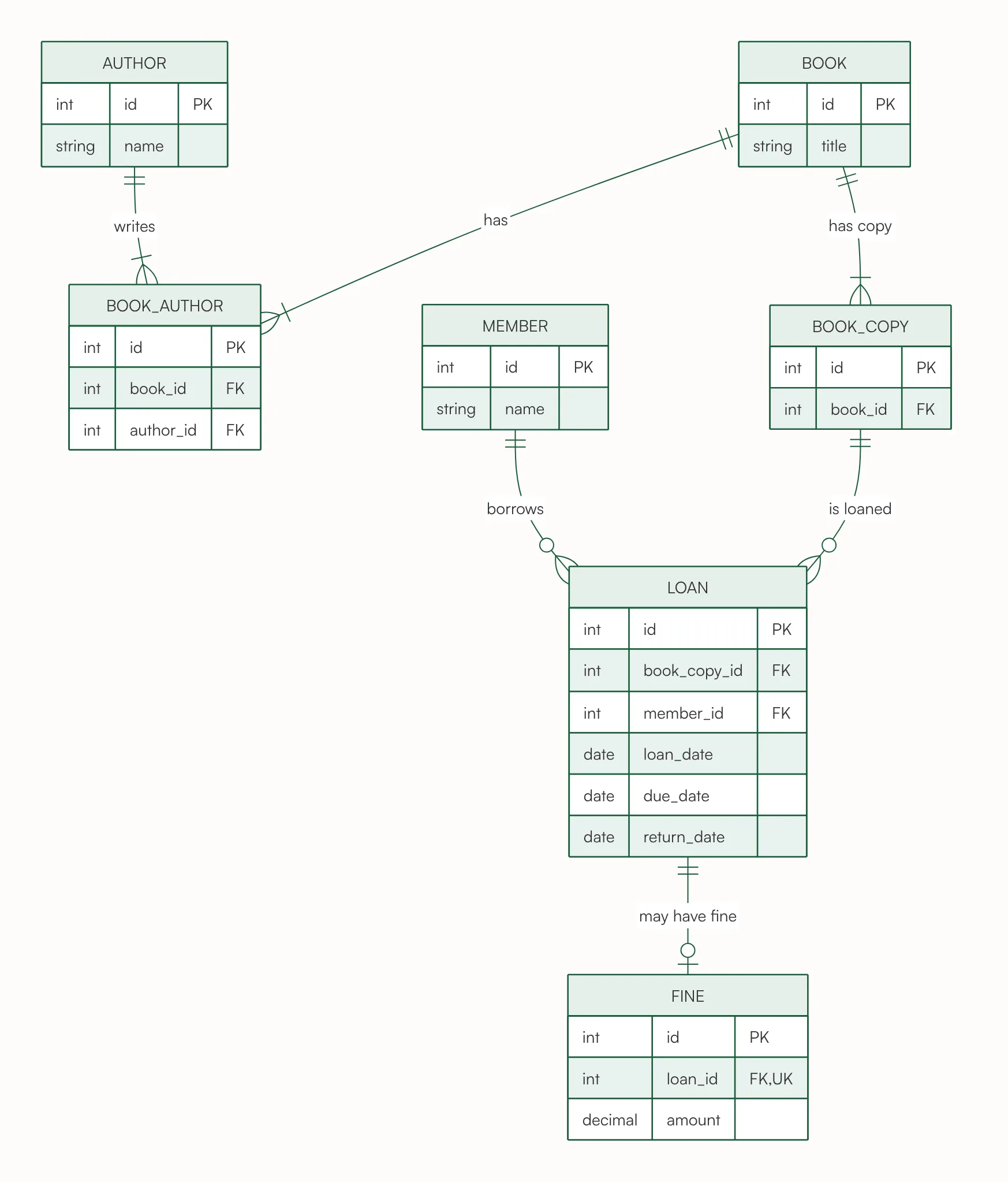
The most asked-for ER diagram in database courses. Solution: books and authors are many-to-many (a book has one or more authors, an author can write many books), so BOOK_AUTHOR sits between them with a foreign key to each. The library lends copies, not titles: BOOK_COPY holds book_id, and each loan is of exactly one copy, by exactly one member. A copy can be lent zero or more times over the years, and a member can borrow zero or more times.
LOAN and FINE are one-to-one with an optional end: a loan has zero or one fine (the circle at FINE), and each fine belongs to exactly one loan, which is why loan_id in FINE is unique.
Text used for this chart
Library management system: each book has one or more authors, and an author can write many books. The library holds several copies of each book. Members borrow copies; each loan records the loan date, the due date and the return date. A loan returned late can have one fine.
4. University ER Diagram: Students, Courses and Enrollments
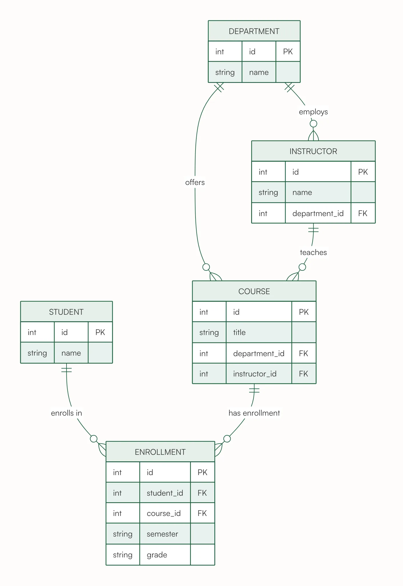
Solution: students and courses are many-to-many: a student takes many courses and a course has many students. Because each enrollment has its own data, the semester and the grade, it becomes an entity of its own, ENROLLMENT, with student_id and course_id. Each course is offered by exactly one department and taught by exactly one instructor, and each instructor works in exactly one department; on the other side, a department offers zero or more courses and employs zero or more instructors.
Text used for this chart
University database: students enroll in courses, and each enrollment records the semester and the grade. Each course belongs to one department and is taught by one instructor. Instructors work in one department.
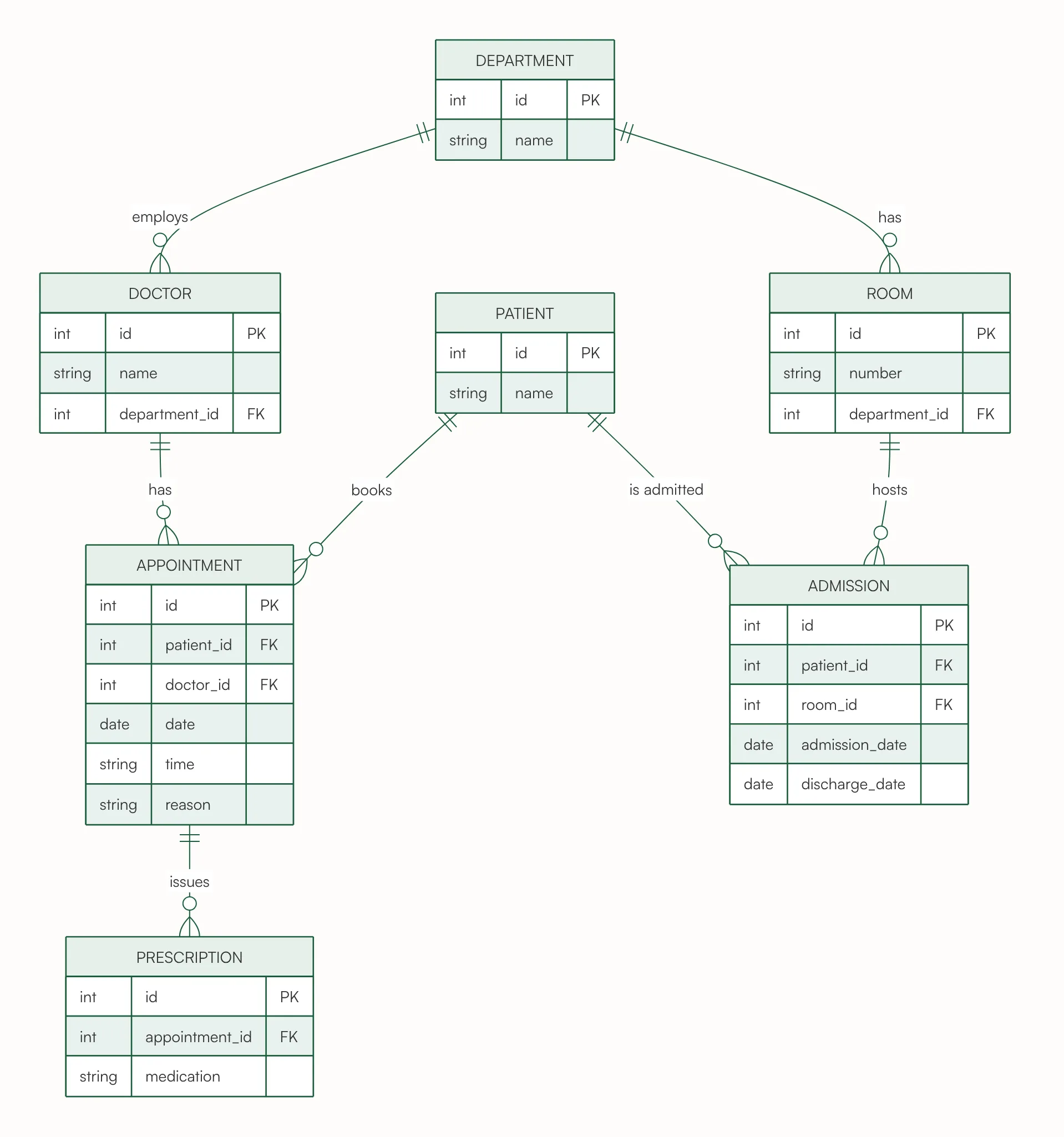
Solution: each doctor works in exactly one department, and each room belongs to exactly one department. An appointment brings together one patient and one doctor, with its date, time and reason; a patient books zero or more appointments and a doctor has zero or more. An appointment issues zero or more prescriptions, and each prescription comes from exactly one appointment. ADMISSION links a patient to a room for a stay, with the admission and discharge dates, so the same patient can be admitted many times and the same room hosts many stays.
Text used for this chart
Hospital management system: each doctor works in one department. Patients book appointments with doctors; an appointment has a date, a time and a reason. A doctor can write prescriptions at an appointment. Patients can be admitted to a ward room, with an admission date and a discharge date. Each room belongs to one department.
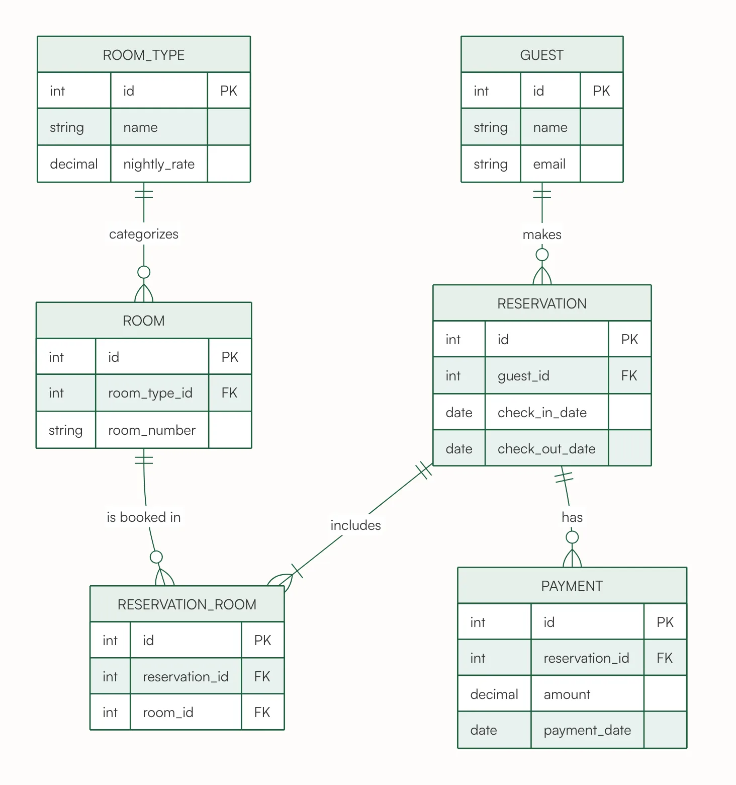
Solution: a guest makes zero or more reservations, and each reservation is made by exactly one guest. A reservation includes one or more rooms, and a room is booked in zero or more reservations over time, so RESERVATION_ROOM sits between them. The nightly rate belongs to the room type, not to each room: every room has exactly one type, and changing the price of all double rooms is one change. A reservation can have zero or more payments, for example a deposit and then the rest.
Text used for this chart
Hotel reservation system: guests make reservations; a reservation can include one or more rooms, each room has a room type with a nightly rate; each reservation can have payments.
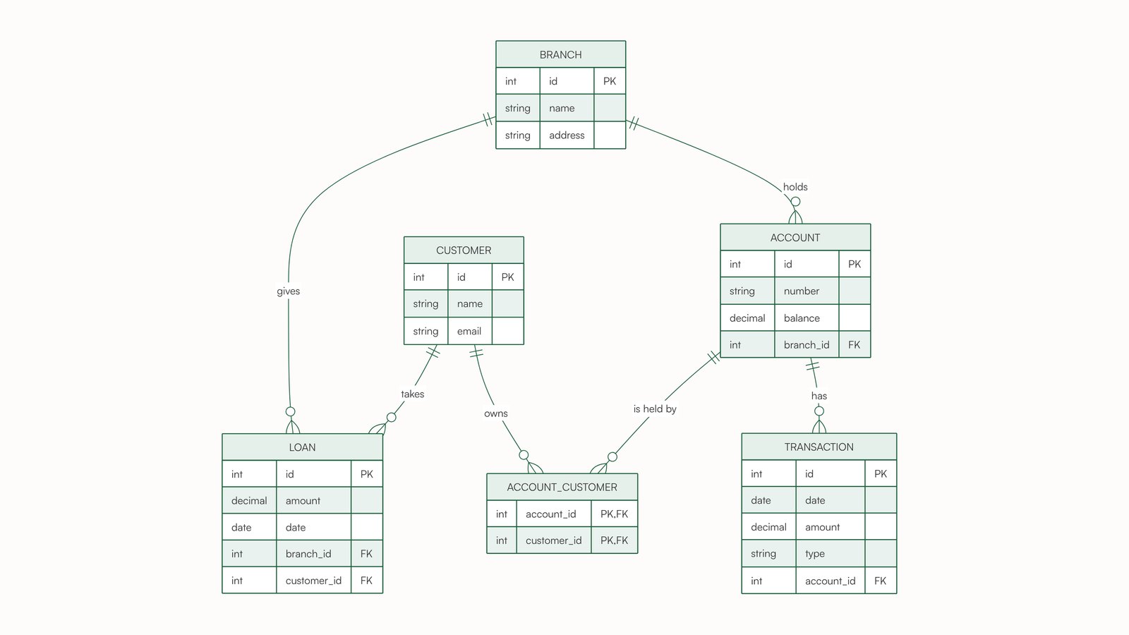
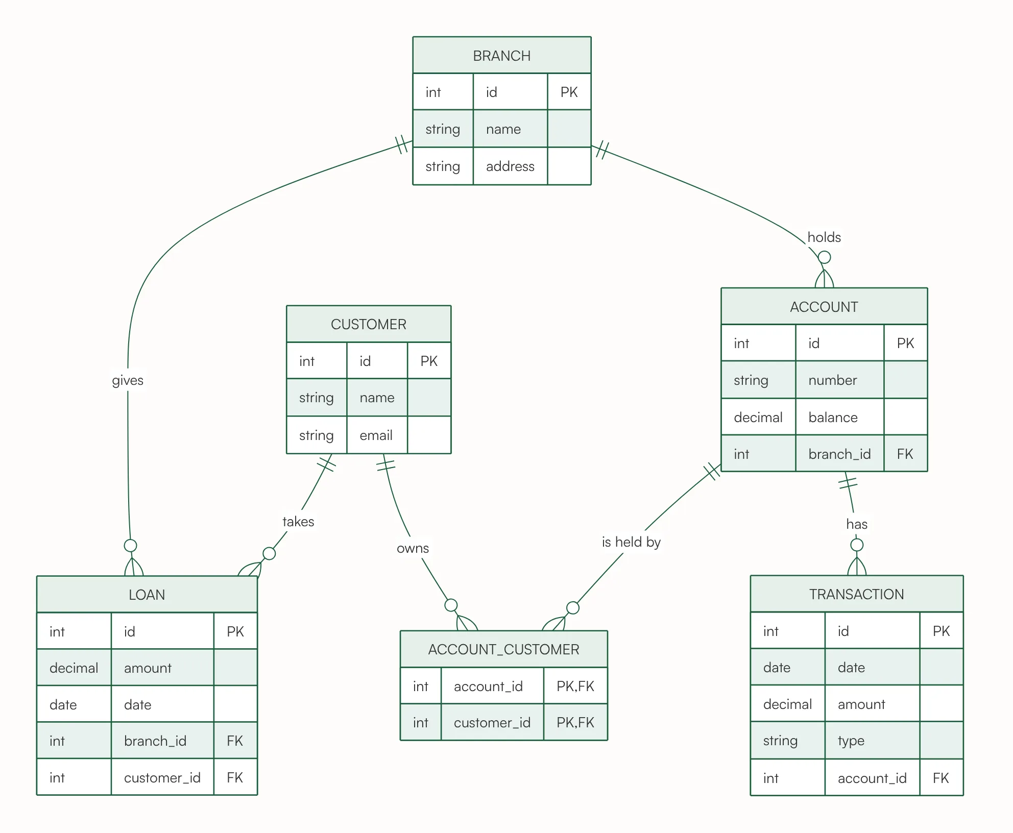
Solution: customers and accounts are many-to-many, because one customer can have several accounts and a joint account has more than one holder. ACCOUNT_CUSTOMER stores each pair, and its primary key is the pair itself (account_id and customer_id are both PK and FK), so the same person cannot be added to the same account twice. Each account belongs to exactly one branch and has zero or more transactions. Each loan is taken by exactly one customer from exactly one branch.
Text used for this chart
Bank database: each branch holds many accounts and gives out loans. A customer can have several accounts, and an account can be held by more than one customer (joint accounts). Each account has many transactions (date, amount, type). Each loan is taken by one customer from one branch.
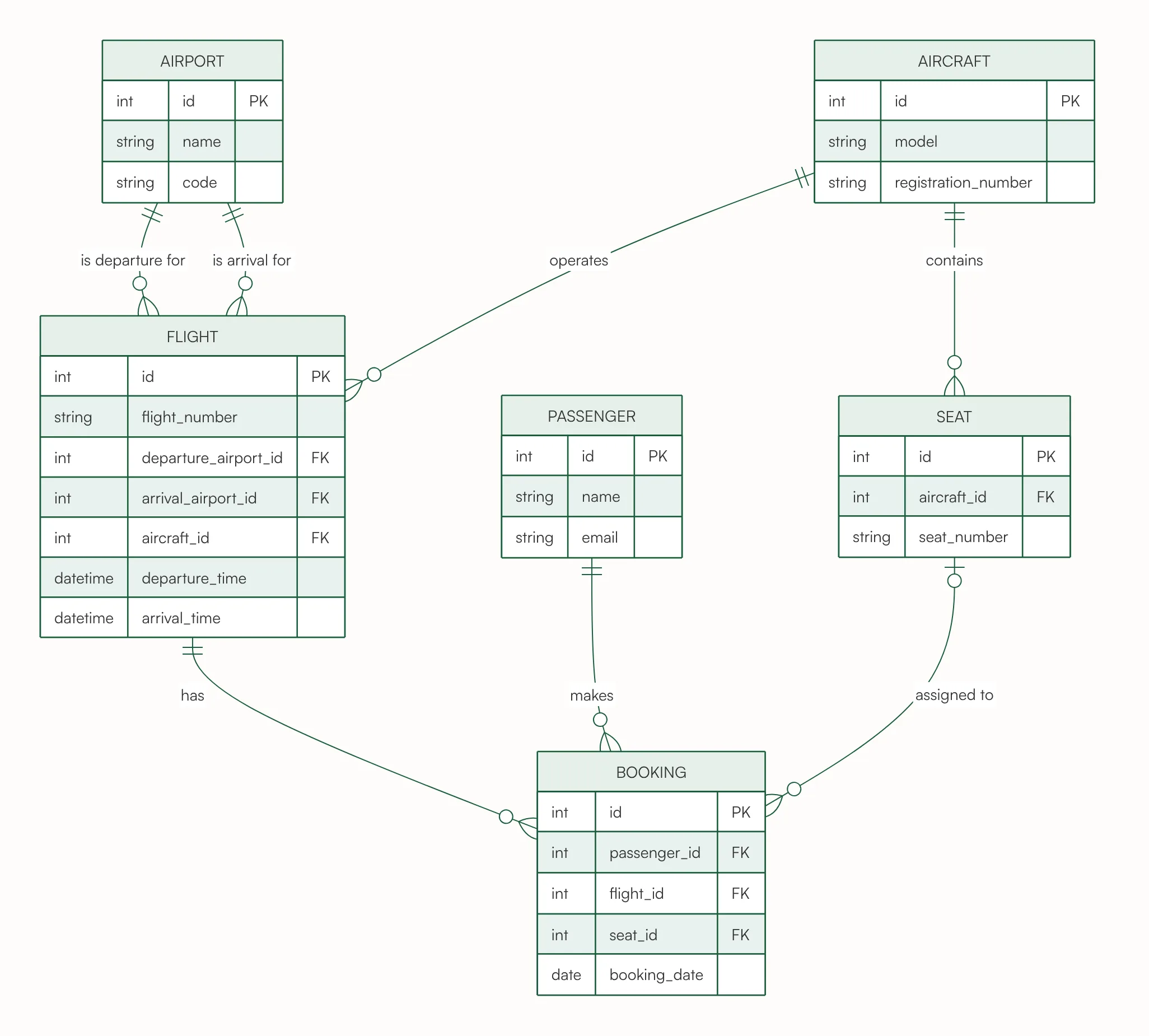
This one has two relationships between the same two entities. Solution: every flight leaves from one airport and lands at another, so FLIGHT has two foreign keys to AIRPORT, departure_airport_id and arrival_airport_id, and there are two lines, each one-to-many. Each flight is operated by exactly one aircraft, and the seats belong to the aircraft. A booking is for exactly one passenger on exactly one flight, and has zero or one seat (the circle at SEAT), so a seat can be picked later; the same seat appears in zero or more bookings, one per flight.
Text used for this chart
ER diagram for an airline reservation system: airports, flights, aircraft, passengers, bookings and seats
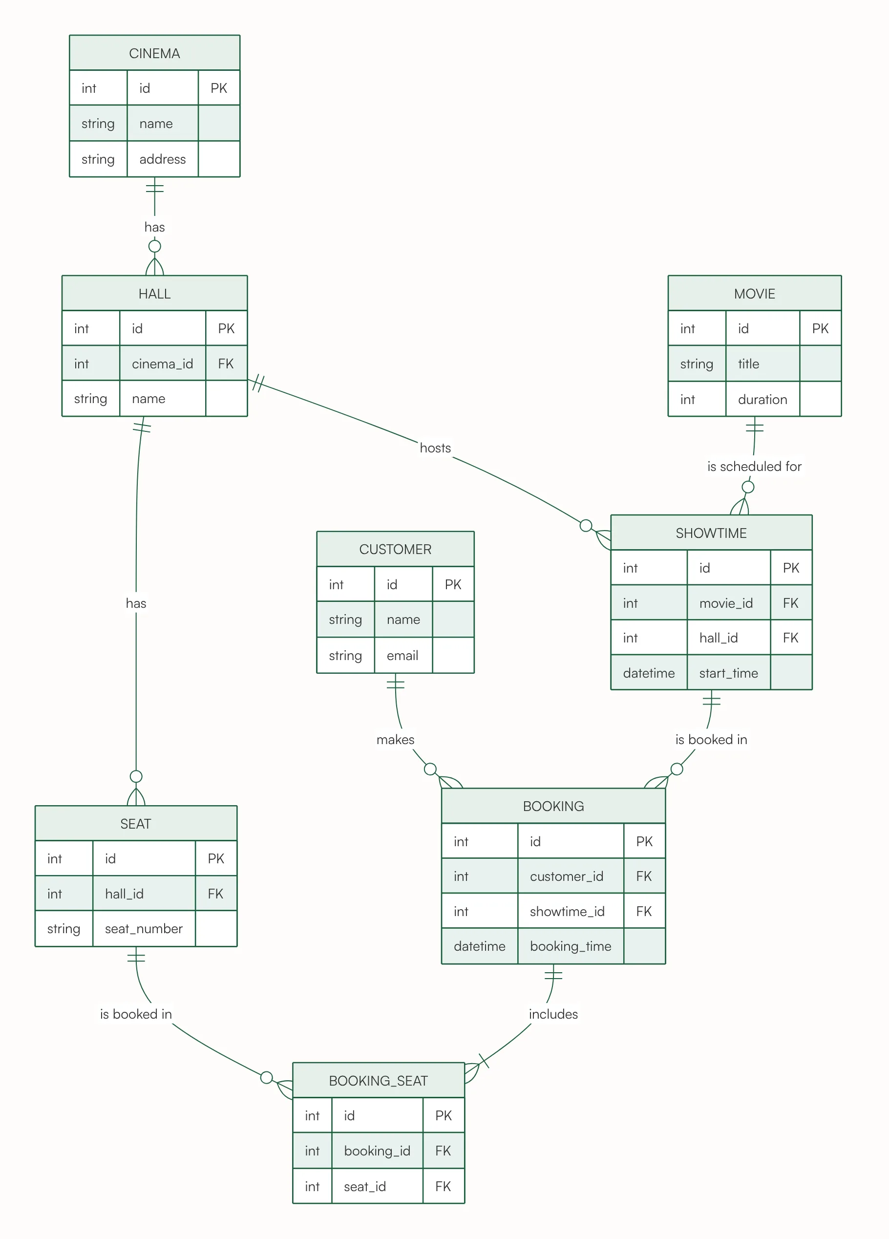
Solution: a cinema has zero or more halls and a hall has zero or more seats, each belonging to exactly one hall. A showtime is one movie in one hall at one start time, so it holds movie_id and hall_id. A customer makes zero or more bookings, each for exactly one showtime, and each booking includes one or more seats through BOOKING_SEAT. A seat is booked many times, once per showtime, which is why it is linked through BOOKING_SEAT and not stored on the booking.
Text used for this chart
Movie ticket booking: a cinema has several halls, each hall has seats. A showtime is one movie in one hall at a time. A customer makes a booking for a showtime and books one or more seats.
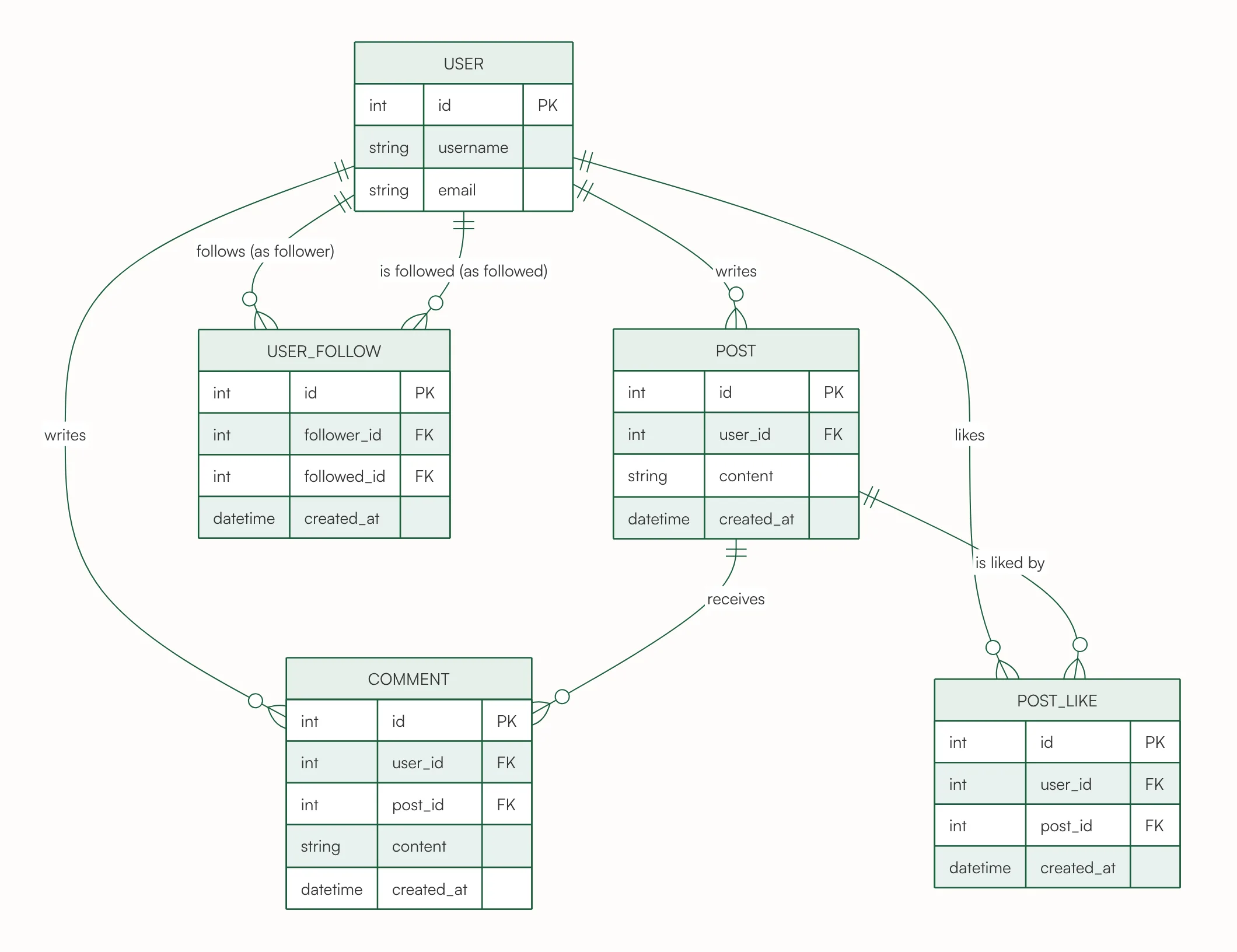
Solution: a user writes zero or more posts and zero or more comments, and each comment is on exactly one post. Likes are many-to-many between users and posts, so each like is a row in POST_LIKE. Following is a relationship of USER with itself: one user follows many others and is followed by many. USER_FOLLOW stores it with two foreign keys to USER, follower_id and followed_id, which is why two lines run from USER to USER_FOLLOW.
Text used for this chart
Social media app: users write posts, users comment on posts, users like posts, and users follow other users.
11. Company ER Diagram: Employees, Departments and Projects
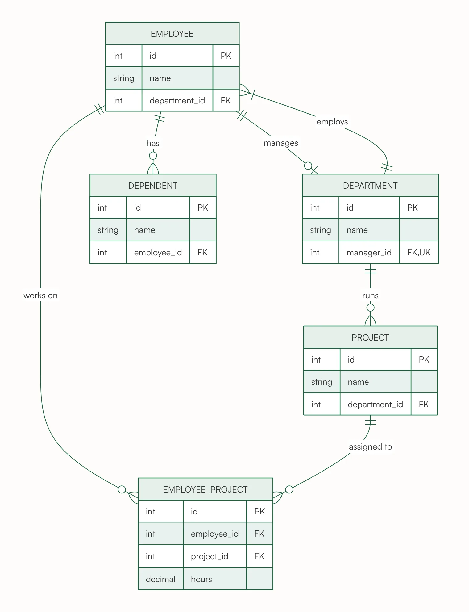
The classic company database from database textbooks, and a hard one, because EMPLOYEE and DEPARTMENT are linked twice. Solution: each employee works in exactly one department, and a department employs one or more employees (department_id in EMPLOYEE). Each department is also managed by exactly one employee, and an employee manages zero or one department (manager_id in DEPARTMENT, unique). Employees and projects are many-to-many with their own data, the hours, so EMPLOYEE_PROJECT is an entity. Each project is run by one department, and an employee has zero or more dependents.
Text used for this chart
Company database: each employee works in one department, and each department has one manager who is an employee. Employees work on projects, and we record the hours each employee works on each project. Each project is run by one department. Employees can have dependents.
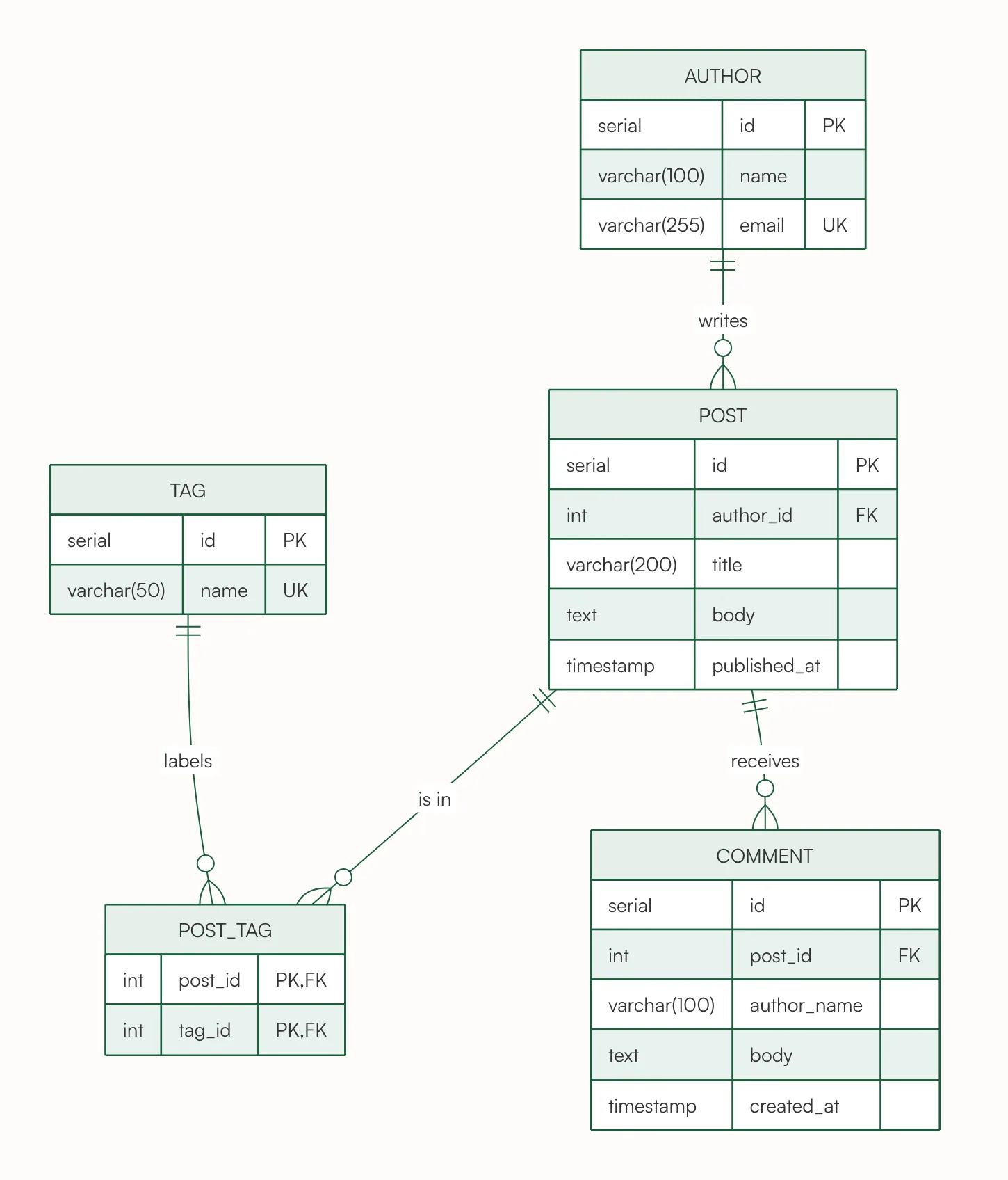
Paste CREATE TABLE statements and the generator draws exactly those tables, columns, types and keys, with one relationship per foreign key, here five tables and four relationships. Table names are shown in the singular, in capitals. Solution: author_id in posts is NOT NULL, so each post has exactly one author. post_tags has a composite primary key (post_id, tag_id), which makes it the link table of a many-to-many relationship between posts and tags. Each comment belongs to exactly one post.
Text used for this chart
CREATE TABLE authors (id SERIAL PRIMARY KEY, name VARCHAR(100) NOT NULL, email VARCHAR(255) UNIQUE);
CREATE TABLE posts (id SERIAL PRIMARY KEY, author_id INT NOT NULL REFERENCES authors(id), title VARCHAR(200), body TEXT, published_at TIMESTAMP);
CREATE TABLE tags (id SERIAL PRIMARY KEY, name VARCHAR(50) UNIQUE);
CREATE TABLE post_tags (post_id INT REFERENCES posts(id), tag_id INT REFERENCES tags(id), PRIMARY KEY (post_id, tag_id));
CREATE TABLE comments (id SERIAL PRIMARY KEY, post_id INT NOT NULL REFERENCES posts(id), author_name VARCHAR(100), body TEXT, created_at TIMESTAMP);
One-to-many is the most common: one customer, many orders (example 2). The foreign key goes in the entity on the "many" side.
One-to-one: one order and one payment (example 2), one loan and at most one fine (example 3). The foreign key is also unique, marked FK, UK.
Many-to-many: students and courses (example 4), books and authors (example 3), customers and joint accounts (example 7). A database stores it as a table in between, with a foreign key to each side. When the link has data of its own, such as a grade or hours worked, that table is an entity in its own right (ENROLLMENT, EMPLOYEE_PROJECT).
An entity related to itself: users following users (example 10). The link table has two foreign keys to the same entity.
How to Make Your Own ER Diagram From an Example
Step 1: Pick the closest example. Start from the system that looks most like yours: a shop, a booking system, a school or a social app.
Step 2: Press Use this text. The ER diagram generator opens with the example's text in its box.
Step 3: Change the text. Say what your system stores and how the things relate. Words like "each", "one or more" and "at most one" set the ends of the lines. You can also write just a topic, such as "gym membership system", or paste your CREATE TABLE statements.
Step 4: Press Generate. The diagram is ready in under 30 seconds, with up to about 12 tables. You can make one diagram a day without an account; a free account gets 16 credits to start and 4 free credits a day, and each diagram uses 4.
Step 5: Download or edit it. Download it as a PNG or SVG, copy its Mermaid code into GitHub, Notion or your docs, or open it in draw.io to move the boxes by hand. These need a free account.
Tips for a Good ER Diagram
Name entities in the singular. CUSTOMER, not CUSTOMERS: each box describes one row.
Give every entity a primary key. Usually id; a link table can use the pair of foreign keys instead, as in examples 7 and 12.
Put the foreign key on the "many" side. The order holds customer_id, never the other way round.
Turn a many-to-many with its own data into an entity. A grade belongs to an enrollment, not to the student or the course.
Check each line both ways. Say it aloud: each order has exactly one customer; each customer has zero or more orders. If either sentence is wrong, so is one end of the line.
Keep one diagram to one area. For a big schema, make one diagram for users and accounts and another for orders and payments.
Quick Answers About ER Diagram Examples
What is an ER diagram with an example? A picture of a database's entities and how they relate. In an online store, CUSTOMER, ORDER and PRODUCT are entities, and "a customer places zero or more orders" is a relationship (example 2).
How do I read an ERD? Read each line from both sides: the symbol at an entity says how many of that entity go with one of the other. Two bars mean exactly one, a circle means there can be none, and a crow's foot means many.
What are the three main types of ERD? Conceptual (entities and relationships only), logical (adds attributes and keys) and physical (adds the database's own column types). Most examples above show keys and simple types; example 12, drawn from SQL, keeps the SQL's own types, as a physical diagram does.
Are these Chen or crow's foot diagrams? Crow's foot, the notation most database tools use. Chen notation draws relationships as diamonds and attributes as ovals; the generator does not draw it.
How do I draw an ER diagram? List the things to store (the entities), give each its attributes and a primary key, then add a line for each relationship and decide both ends. Or describe your system in the ER diagram generator and start from its diagram.
Can I make an ER diagram from SQL? Yes. Paste your CREATE TABLE statements, as in example 12: the diagram shows exactly your tables and one line per foreign key.
Start From the Closest Example
Every database design starts with two questions: what do we store, and how does it relate? Find the example above that looks most like your system, press Use this text and change it, or start from a blank box in the ER diagram generator.
Describe it in a few sentences or paste a list, and get a clean, editable chart in under 30 seconds. Free to try: one diagram a day without an account.